
 English (United Kingdom)
  Italiano (Italia)
Indice
- Dual Joystick Controller: Project Overview
- Parts and Components You'll Need
- Tools and Equipment You'll Need
- Difficulty Level, Build Time and Cost
- The Joysticks
- The Enclosure
- Mounting the Joysticks
- Wiring Diagram and Circuit Connections
- Wiring Up the Controller
- Dupont Connectors: Wiring the Cable Ends
- Crimping the Dupont Contacts
- Connecting the Controller to Arduino Uno
- The PCA9685 PWM Driver Board
- The Complete System: Controller, Arduino and Robotic Arm
- Conclusions and Acknowledgements
Dual Joystick Controller: Project Overview
Getting a 4DOF robotic arm to move smoothly and naturally with Arduino calls for an intuitive interface — one that can translate hand movements into precise commands. In this project we'll build a handheld controller based on two analogue joysticks: one of the most straightforward and effective ways to drive a hobbyist robotic arm, and a great starting point for learning how to control it with Arduino using very little extra hardware.
The end result is a reliable control system that combines dedicated components with fully customisable software logic.
If you haven't assembled your robotic arm yet, you can follow the complete guide I published here: Practical Guide to Assembling a 4 DOF Robotic Arm (by Capitan Farloc). Once the mechanical structure is done, this controller will let you drive all four degrees of freedom in a direct, precise and altogether more engaging way.
Parts and Components You'll Need
To build a DIY joystick controller for a 4DOF robotic arm with Arduino, you only need a handful of affordable and easy-to-source components:
- 2 dual-potentiometer analogue joysticks salvageable from old consoles, electronic surplus shops, or available online
- 1 weatherproof outdoor junction box (IP55), the kind commonly used in domestic electrical installations, or any other suitable plastic enclosure
- 1 multicore cable with at least 6 differently coloured conductors (audio signal or home automation cable works well)
- 2.54mm pitch crimp Dupont connectors 1 x 4-pin male housing and 1 x 2-pin male housing, with their respective crimp contacts
- 4 x 100nF capacitors for filtering the analogue signal on Arduino's ADC inputs
- 1 Arduino Uno (or compatible board)
- 1 PCA9685 16-channel PWM driver board with I2C interface
- Solder and copper wire for the internal jumpers inside the controller
Tools and Equipment You'll Need
To assemble and wire up the controller, you won't need anything beyond the standard tools found in most hobbyist workshops:
- Soldering iron and solder for soldering the potentiometer terminals and the internal jumper wires
- Multimeter essential for checking continuity and voltage levels before connecting the cable to Arduino
- Drill with a step drill bit for making the holes in the junction box for the joystick shafts and the multicore cable
- Wire strippers or electrician's scissors for cutting and stripping the conductors of the multicore cable
- Crimping tool or needle-nose pliers for crimping the Dupont contacts onto the wires. A dedicated crimping tool gives cleaner and more consistent results, but needle-nose pliers will do the job if that's all you have to hand
Difficulty Level, Build Time and Cost
Difficulty: Easy
This project is well within reach of anyone with a basic familiarity with low-voltage electronics and simple DIY work. No advanced skills are required, but you'll need to take your time and be careful with the wiring.
Build Time: 4–8 hours
The actual time will depend on:
- how long it takes to prepare and drill the enclosure
- how tidy you want your wiring to be
- the number of soldering joints involved
Total Cost: £5–15
Several components can be salvaged or sourced second-hand, which can bring the cost down considerably.
The Joysticks
This controller came about from the need for a practical tool to study how to interface with and control the movements of a 4DOF robotic arm using Arduino Uno.
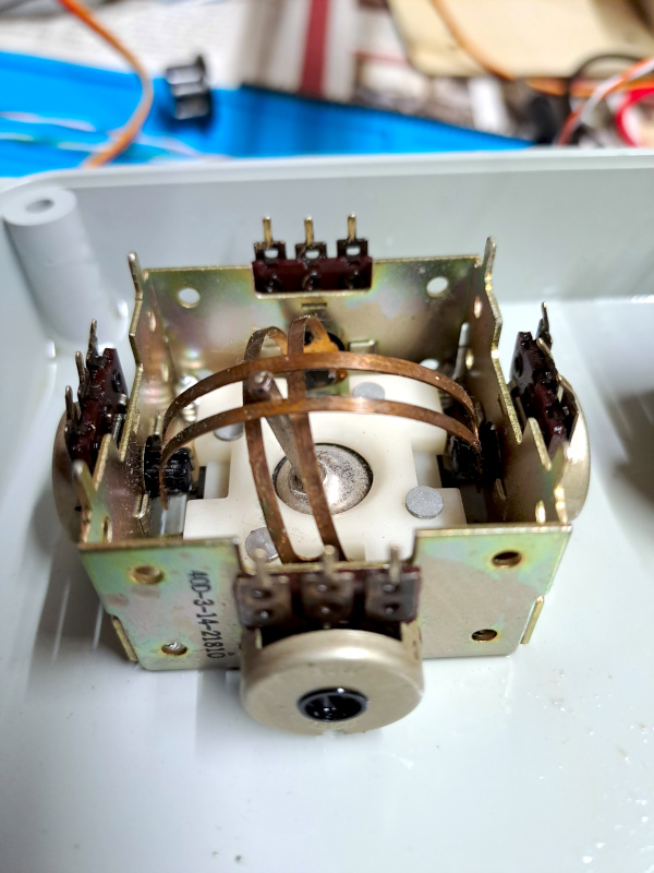
To build it, I dug out two analogue joysticks I'd picked up years ago at an electronics surplus shop and never got around to using. Alternatively, you can use joysticks salvaged from old consoles or PC controllers, as long as they work on the basis of two potentiometers — one for the X axis and one for the Y axis — whose resistance varies as the stick is moved.
That's precisely what makes them suitable for this project: the position of the stick translates directly into an analogue value that Arduino can read.
The Enclosure
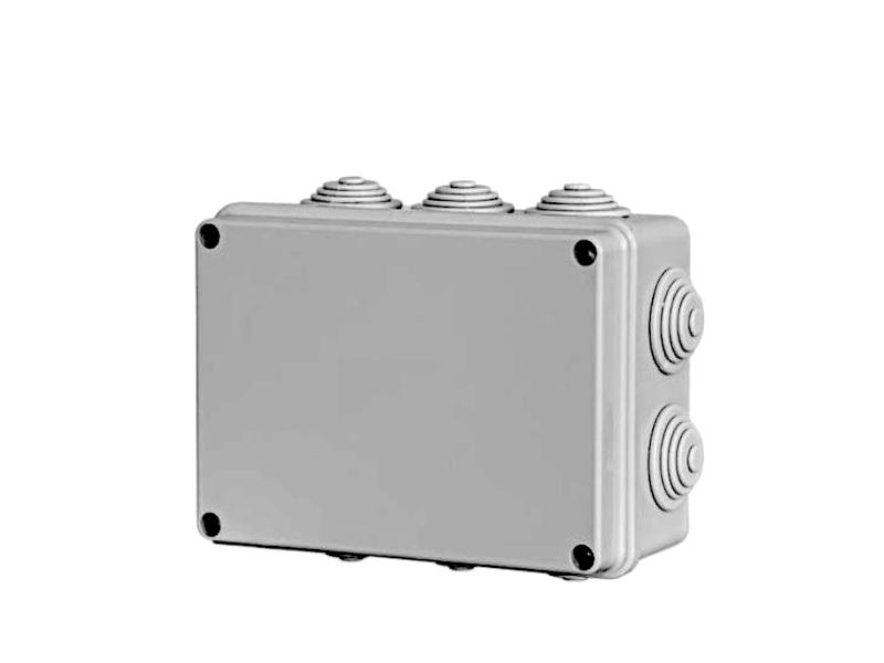
Since the joysticks have no casing of their own, I needed to find a suitable box to house them and keep all the wiring tidy. I went with a weatherproof outdoor junction box, the kind you'd normally find in domestic electrical installations.
The reasons behind the choice are purely practical: it's cheap, easy to find in any electrical supply shop, and the plastic is sturdy enough to be robust while still being easy to work with — which comes in handy when you need to drill or cut the openings for the joystick shafts.
As a bonus, the cable glands on the sides — normally used for routing electrical cables — turned out to be just as useful for managing the project wiring.
Mounting the Joysticks
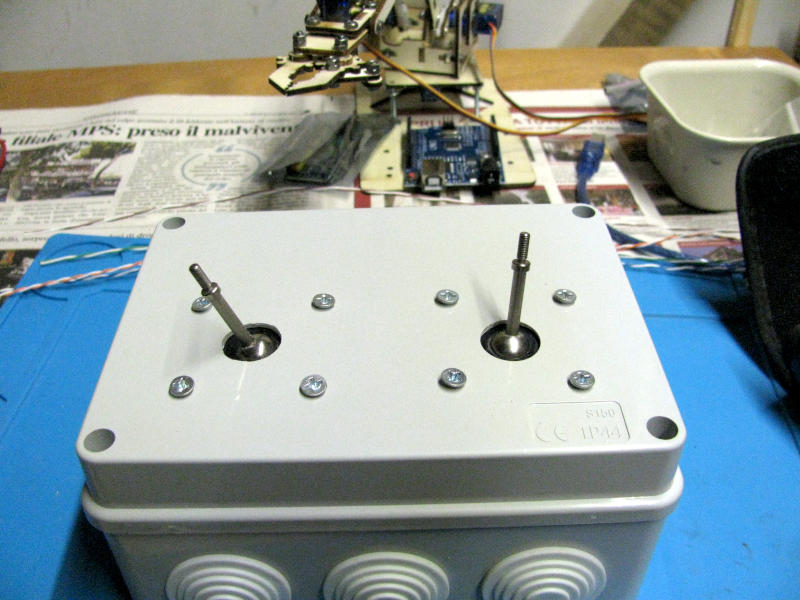
To fit the two joysticks onto the enclosure, I drilled two circular holes in the lid for the joystick shafts, along with the corresponding fixing holes for the mounting screws. As you can see in the photo, the joysticks sit flush against the inside of the lid, with only the shafts poking through — giving the finished controller a clean and compact look. The lid's flat surface also makes it comfortable to rest your hands on while operating the joysticks.
Wiring Diagram and Circuit Connections
Arduino's analogue inputs read a voltage between 0 and 5V and convert it, via a 10-bit ADC, into a whole number between 0 and 1023. The analogRead(pin) function returns 0 at 0V and 1023 at 5V, with all intermediate values distributed linearly in between.
To take advantage of this, all you need to do is bring the two voltage references available on Arduino into the controller: GND (0V) and 5V. By connecting these across the two ends of each potentiometer, the wiper becomes a variable voltage divider: the voltage taken from the wiper, and therefore the value returned by analogRead(), will accurately reflect the position of the stick at any given moment.
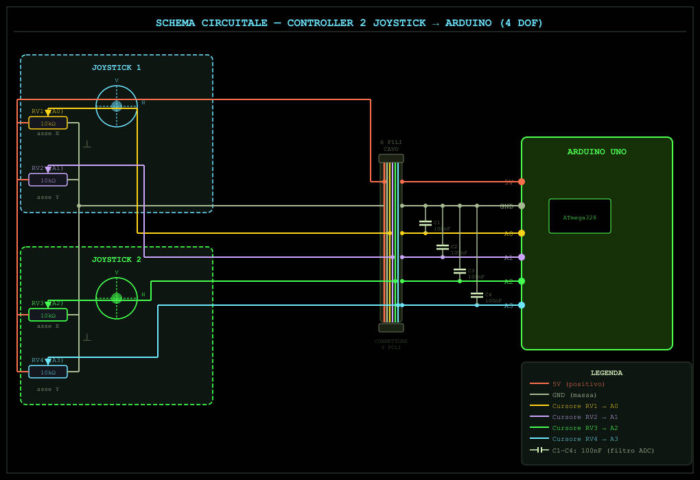
Each joystick has two potentiometers, one for the X axis and one for the Y axis. With two joysticks we end up with four independent analogue signals, each mapped to one of Arduino's analogue inputs, giving us the real-time position of both sticks.
Below is the full wiring diagram for all four potentiometers. The four capacitors C1÷C4 (100nF each) shown in the diagram are there to filter the analogue signal before it reaches the ADC, reducing noise on the readings.
Wiring Up the Controller
To connect the controller to Arduino you'll need a cable with at least six conductors: two for the power supply (5V and GND, shared between both joysticks) and four for the analogue signals, one for each axis, X and Y, of each joystick. You don't need heavy-gauge wire: since we're dealing with very low-current analogue signals, a lightweight multicore signal cable is more than adequate — the kind commonly used for audio installations or home automation systems works perfectly.
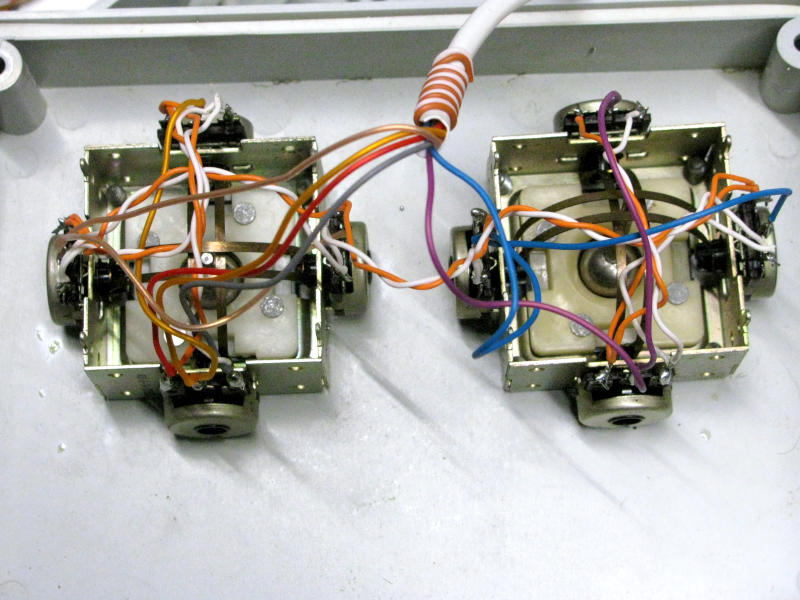
It's good practice to use a cable with differently coloured conductors and to stick to the same colour-to-signal association throughout the entire wiring, including the internal jumpers inside the controller. This seemingly obvious tip can save you a lot of head-scratching when debugging unexpected behaviour.
Bear in mind that the longer the cable, the more susceptible it is to electromagnetic interference, which shows up as instability in the analogue readings. It's therefore advisable to keep the cable length under one metre or alternatively, make sure the 100nF filter capacitors on Arduino's ADC inputs (shown in the wiring diagram) are actually in place.
In my case, the joysticks have two potentiometers per axis, not a universal feature, but fairly common in vintage models. I chose to wire them in parallel in pairs: this slightly lowers the total resistance seen by the ADC input, but more importantly it averages out any small differences between the two elements, resulting in a more stable and noise-free reading.
Dupont Connectors: Wiring the Cable Ends
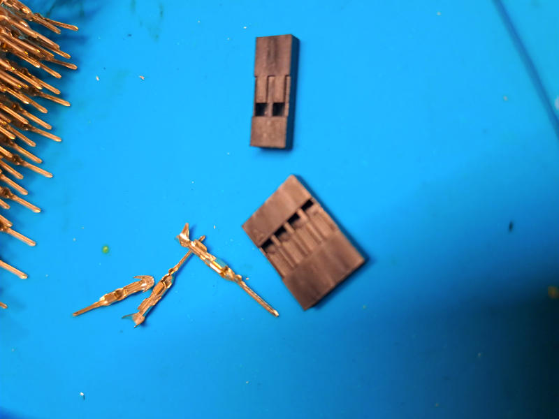
To terminate the multicore cable I went with 2.54mm pitch Dupont connectors — the de facto standard in the Arduino world and hobbyist electronics in general. These are crimp-on connectors made up of two parts: a plastic housing, available in various configurations from 1 to n pins, and gold-plated metal contacts that are crimped onto each individual wire and then inserted into the housing until they click into place.
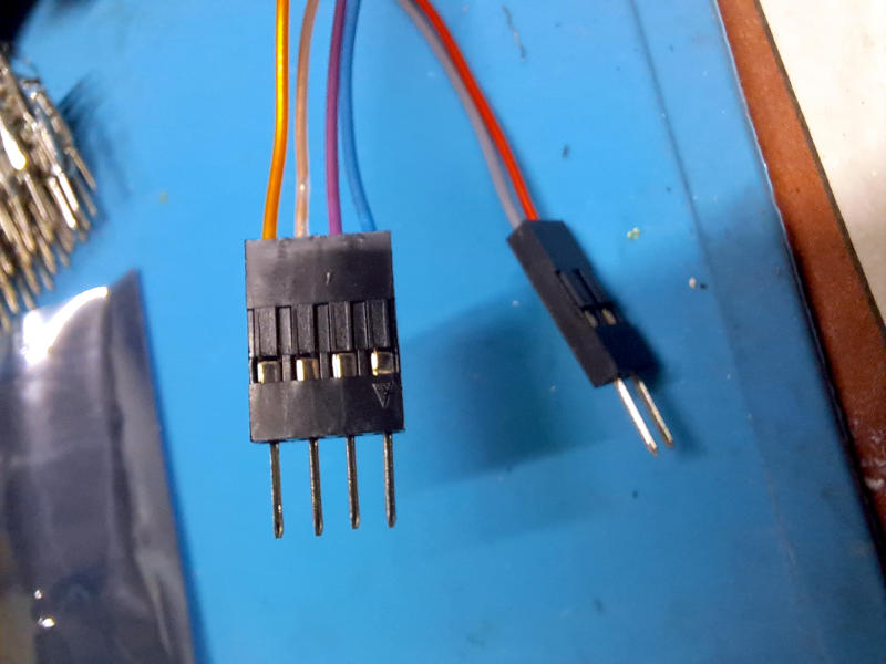
For this project I used two: a 4-pin connector for the four analogue signals (X and Y axes of both joysticks) and a 2-pin connector for the power supply (5V and GND). Splitting them into two separate connectors has a practical advantage: it makes it physically impossible to accidentally plug the power wires into Arduino's analogue inputs, which significantly reduces the risk of damaging the board.
Crimping the Dupont Contacts
Once the conductors of the multicore cable have been stripped back by about 2–3mm, the metal contacts are crimped onto each wire using a dedicated crimping tool or, if you don't have one to hand, a pair of needle-nose pliers will do the job, though it takes a bit more patience. Each contact is then inserted into the plastic housing from the rear, making sure you have the orientation right, until you feel the satisfying click that tells you the locking tab has engaged properly.
The end result is a clean, reliable push-fit connection that can be unplugged easily whenever you need to make changes or carry out maintenance a definite advantage over soldering directly onto Arduino's pins.
Connecting the Controller to Arduino Uno
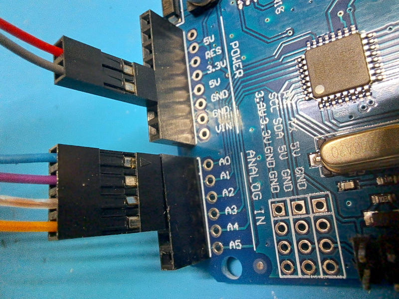
Once the crimping is done, connecting everything to Arduino Uno is straightforward: the 2-pin connector plugs into the 5V and GND pins on the POWER header, while the 4-pin connector slots onto pins A0, A1, A2 and A3 on the ANALOG IN header. The 2.54mm pitch Dupont connectors are a perfect fit for Arduino Uno's pin headers, which come with standard female pins as standard.
One important thing worth mentioning for anyone thinking of using an Arduino Nano instead of the Uno: on the Nano the pin headers are male, so the wiring itself doesn't change, but the connectors you crimp onto the cable will need to be female rather than male, so they can plug onto the board's pins correctly. It's a simple difference, but one to bear in mind right from the cable assembly stage, otherwise you'll end up having to redo it from scratch.
The PCA9685 PWM Driver Board
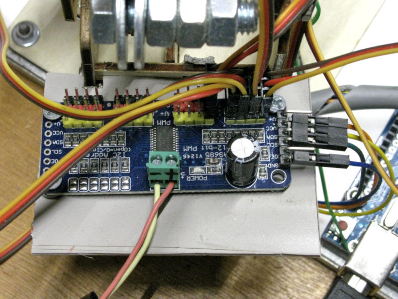
Even though the robotic arm only uses four MG90S mini servos, it's not a good idea to connect them directly to Arduino Uno's PWM pins. Each servo draws a current that, especially under load, can easily exceed what the board's pins can safely supply, with the very real risk of permanently damaging your Arduino.
The solution used in this project is a driver board based on the PCA9685 chip, a 16-channel independent PWM controller. This board takes care of generating the PWM signals for each servo on its own, powering them from a dedicated external power supply visible in the green power connector in the photo and taking that job completely off Arduino's hands.
The most significant advantage from a wiring point of view is that the PCA9685 talks to Arduino over I2C, a two-wire serial protocol (SDA and SCL) plus power. This means that regardless of how many servos are connected, only two of Arduino's pins are used, leaving all the remaining ports free for future expansions. The board's I2C address can also be configured via the solder pads visible on the left edge, which makes it possible to connect up to 62 PCA9685 boards on the same bus for a theoretical total of 992 independent PWM channels.
The Complete System: Controller, Arduino and Robotic Arm
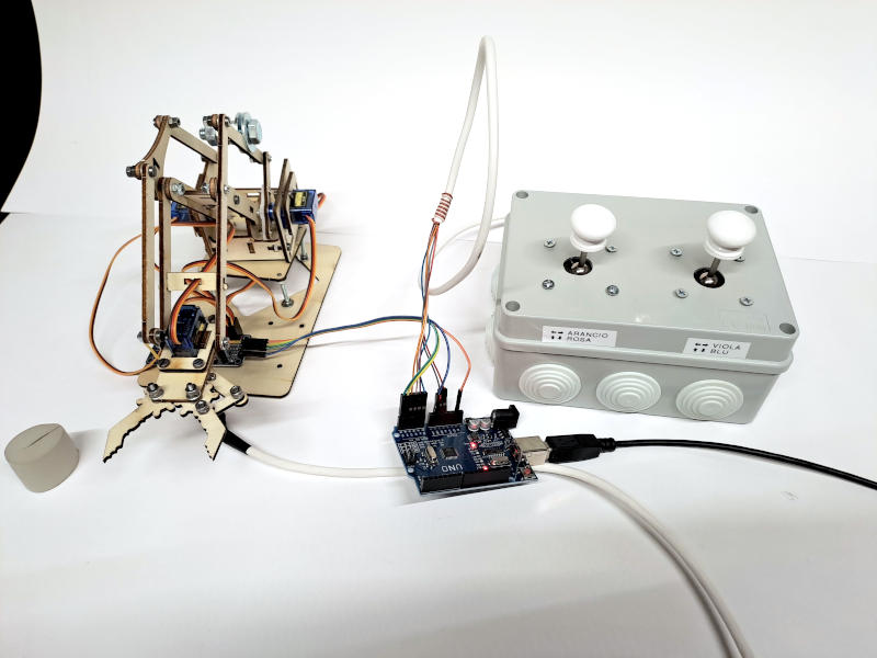
With the controller fully assembled and wired up, the 4DOF robotic arm is finally ready to be operated manually. The system as a whole consists of three elements connected in series: the dual joystick controller, Arduino Uno, and the robotic arm with its PCA9685 driver board.
The signal flow is simple and straightforward: the joystick sticks generate four variable analogue voltages that the multicore cable carries to Arduino Uno's A0÷A3 inputs. The firmware reads these values, processes them, and translates them into PWM commands that are sent over I2C to the PCA9685 board, which drives the arm's four servo motors with the required precision and smoothness.
On the front panel of the controller you can clearly see the labels for the two joysticks, ORANGE/PINK and PURPLE/BLUE, which match the colours of the internal wiring and make it immediately obvious which stick controls which movements. It's a small touch that might seem trivial, but it turns out to be genuinely useful during the first few operating sessions and even more so when debugging the firmware.
Arduino Uno is powered directly via the USB cable connected to the computer, which also serves for uploading and updating the firmware.
Conclusions and Acknowledgements
Thanks for following this guide on building a dual joystick controller for a 4DOF robotic arm. Understanding the components involved, getting to grips with how analogue joysticks work, and putting together a tidy and reliable wiring job are the essential foundations you'll need before moving on to the next stage: the programming.
The controller we've built together is now complete on the hardware side, but to actually get it up and running you'll need to upload the firmware to Arduino Uno the code that reads the joystick analogue signals and translates them into smooth, precise movements of the robotic arm. That part the Arduino sketch, the PCA9685 library and the mapping of movements to the joystick axes will be covered in a dedicated follow-up article, "Tutorial – Arduino Programming for the Dual Joystick Controller", which I'll be publishing soon.
If you've found this guide useful and would like to explore more projects in robotics and hobbyist electronics, feel free to browse the other content in the Electronics and Robotics section of the site, where you'll find plenty more practical guides and step-by-step tutorials.
I care a great deal about the quality and originality of everything I publish, so I'd rather my content wasn't copied or republished elsewhere. That said, if you think this guide could be useful to other people, I'd be really pleased if you shared the link to this page it's the best way to spread the word and support the work that goes into every article.
Happy Building, Everyone!
Luciano (Capitan Farloc)