
 English (United Kingdom)
  Italiano (Italia)
Indice
- DIY Bluetooth Karaoke Speaker: A Project That Started by Accident
- Parts and Components You'll Need
- Tools and Equipment You'll Need
- Difficulty Level, Build Time and Cost
- The Salvaged Speakers: Where the Project Began
- Choosing the Right Plywood for a DIY Speaker Cabinet
- The Bluetooth Amplifier Board with Microphone Input
- Designing the Cabinet in FreeCAD: From Graph Paper to 3D Model
- Optimized Cut List: Getting All the Panels Out of a Single Sheet
- Cutting the Panels: From a Single Sheet to Individual Pieces
- Biscuit Joinery: The Key to an Airtight Speaker Cabinet
- Gluing and Clamping: the Cabinet Takes Shape
- Marking Out the Front Panel: Speaker Cutouts and Recesses
- Routing the Woofer Recess: an Improvised Circle Jig That Actually Works
- Cutting the Speaker Holes with the Jigsaw
- The Completed Front Panel: Speaker Cutouts and Recesses All Done
- Painting: Primer and Matte Black Paint Applied with a Roller
- Mounting the Speakers: Bolts and Lock Nuts for Vibration-Proof Fastening
- Stapling the Metal Speaker Grille with a Pneumatic Staple Gun
- The L-Shaped Trim and Draft Seal Strip: the Front Panel Solution
- The Amplifier Board Cutout: Routing the Top Panel
- The Internal Airtight Box Under the Amplifier Board: a Detail You Can't Overlook
- Internal Wiring: 3-Way Crossover and Speaker Connections
- The Completed DIY Bluetooth Karaoke Speaker: the Finished Result
- Conclusions and Acknowledgements
DIY Bluetooth Karaoke Speaker: A Project That Started by Accident
It all started with a get-together with friends and the idea of organizing a karaoke night. While shopping around for a compact system with a built-in amplifier and speakers, I came across one that looked really sharp, all black, with the speakers visible behind a metal grille, but the price tag, over $200, convinced me to go a different route: build one myself.
Building a DIY karaoke speaker gave me the chance to hit three goals at once: keep the costs down, repurpose the speakers from an old speaker cabinet that had been sitting unused in the attic for years, and (why not) enjoy the whole building process along the way.
The end result is a compact system with a Bluetooth amplifier board, a microphone input with independent volume control, and a 3-way speaker setup with a passive crossover, all housed in a black-painted plywood cabinet. In this guide I'll walk you through how I designed and built it from scratch, covering all the technical details and practical solutions I came up with along the way.
Parts and Components You'll Need
Here's everything you'll need to build your own DIY Bluetooth karaoke speaker:
For the wooden cabinet:
- 1 sheet of 15mm poplar plywood, approximately 48" x 24" (120 x 60cm) — available at hardware stores or lumber yards
- Biscuits (wood joining biscuits) for panel joints, dowels work just as well as an alternative
- Wood glue (PVA), to bond the structure and ensure an airtight seal
- 1 square wooden strip, for the rear panel support
- 10x10mm black plastic L-shaped trim, for the front panel housing
- Rubber door draft seal strip, for an airtight seal on the front and rear panels
- Wood screws and bolts with nuts and lock nuts, for securing the front and rear panels and the speakers
- Staples or U-nails, for securing the protective grille
- Water-based wood primer/sealer, to prepare the surfaces before painting
- Matte black water-based paint, for the final finish (two coats)
- 1 black painted metal speaker grille
For the electronics:
- Recycled speakers: 1 x 10" (25cm) acoustic suspension woofer, 1 midrange and 1 tweeter, alternatively, 1 or 2 full-range speakers with a wider frequency response can be used
- 1 passive 3-way crossover (recycled), already assembled and working, needed if you're using 3 separate speakers as in this build
- 1 Bluetooth amplifier board with microphone input, available on AliExpress for under $10
- Speaker wire for the internal connections between the amplifier, crossover and speakers
Tools and Equipment You'll Need
This project calls for a basic set of woodworking and electronics tools — though a few extra tools will make the job a lot easier:
Woodworking tools:
- Table saw or miter saw, for cutting the plywood panels — a handheld circular saw or a jigsaw with a guide rail works fine as an alternative
- Biscuit joiner, for cutting the biscuit slots — alternatively, dowel joints can be made using a doweling jig
- Router, for cutting the speaker recesses in the front panel
- Jigsaw, for cutting the speaker pass-through holes
- Drill, for pilot holes for the wood screws and through-holes for the speaker bolts
- Pneumatic staple gun, for securing the metal speaker grille — a manual staple gun or U-nails hammered in by hand work just as well
- Woodworking clamps, for holding the panels in place during gluing
- Carpenter's square and tape measure, essential for accurate measuring and marking
- Short-nap paint roller, for applying the primer and paint
- Brush, for applying the wood glue
Electronics tools:
- Soldering iron and solder, for the electrical connections between the speakers and the crossover
- Multimeter, for checking all connections before closing up the cabinet
- Flathead and Phillips screwdrivers
Difficulty Level, Build Time and Cost
| Difficulty | Intermediate |
| Build time | 3 – 4 days |
| Materials cost | $20 – 50 |
This project requires a reasonable familiarity with woodworking, particularly with using a router and a biscuit joiner, plus a basic understanding of electronics for wiring up the speakers, crossover and amplifier board. None of these are particularly complex operations, but they do require care and precision, especially during the gluing stage where an imperfect seal would compromise the performance of the acoustic suspension woofer.
The estimated build time of 3–4 days covers the panel cutting and cabinet assembly, painting including drying time between coats, and the final electronics wiring. Those with prior woodworking experience will likely get it done faster.
The cost above covers consumable materials only — plywood, paint, glue, screws and miscellaneous hardware. The Bluetooth amplifier board from AliExpress comes in at under $10 and is by far the most cost-effective choice for this type of build. The speakers and crossover used in this project were salvaged from an old cabinet: anyone buying these new should budget extra depending on the quality of components they go for.
The Salvaged Speakers: Where the Project Began
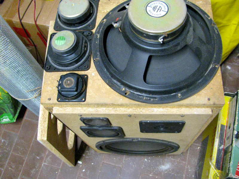
Before even thinking about the cabinet, the project started with the speakers. Sitting in the attic for years was a hand-built speaker cabinet from my younger days — rough around the edges aesthetically, but technically complete: a 10" (25cm) acoustic suspension woofer, a midrange driver and two tweeters, one of which is a piezoelectric type, along with a passive 3-way crossover. Repurposing these components is what made the project both cost-effective and technically interesting. In the photo you can also see the metal grille rolled up on the left-hand side, already earmarked as the ideal solution for protecting the exposed speakers.
Choosing the Right Plywood for a DIY Speaker Cabinet
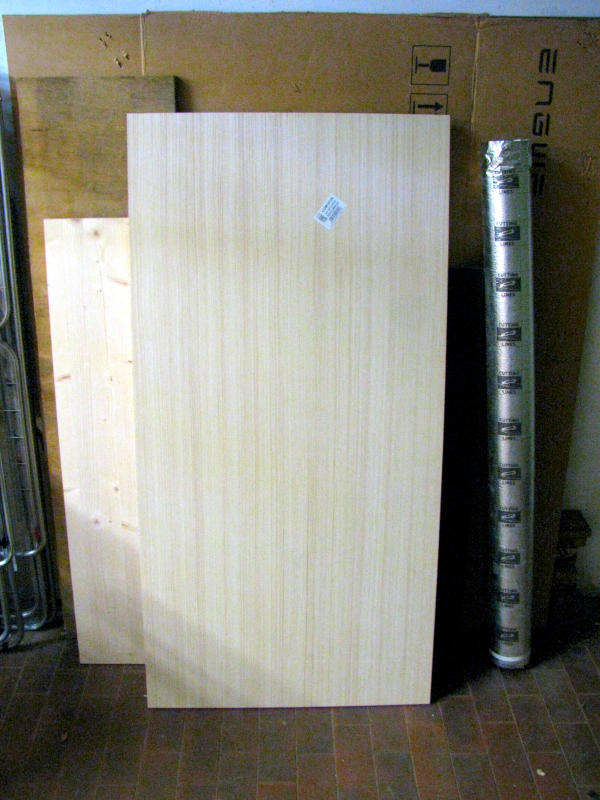
For the cabinet construction I went with a sheet of 15mm poplar plywood, approximately 48" x 24" (121 x 61cm). Poplar plywood is a tried-and-tested choice for DIY speaker cabinet builds: it offers an excellent balance of stiffness, light weight and workability, takes well to both routing and painting, and — when properly glued — provides the airtight seal that an acoustic suspension woofer absolutely requires.
The Bluetooth Amplifier Board with Microphone Input
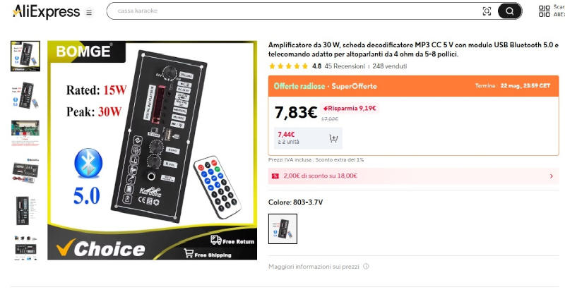
The electronic heart of the project is a Bluetooth amplifier board picked up on AliExpress for under $10. The selection criteria were straightforward: Bluetooth 5.0 connectivity for streaming the backing track from a TV or tablet, a microphone input with independent volume control for the singer, and enough power to drive the available speakers — 15W rated with peaks up to 30W. The board also includes a remote control, a USB MP3 player and an MP3 decoder, making it a complete and versatile solution for a hobbyist karaoke system.
There are several boards of this type available on online stores. The one I used — shown in the screenshot — has a particularly useful feature alongside the standard speaker output: a separate high-pass filtered output specifically designed for a tweeter, which makes it ideal for single or two-speaker setups without the need for an external passive crossover.
Designing the Cabinet in FreeCAD: From Graph Paper to 3D Model
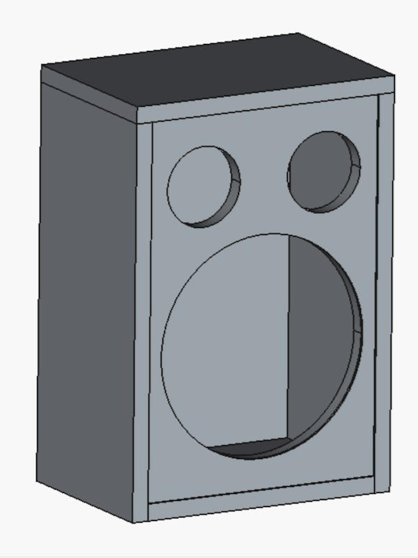
Before cutting a single piece of wood, the cabinet needed to be designed down to the last detail. Setting aside the traditional graph paper sketch, this was the perfect opportunity to learn FreeCAD — a completely free and open source 3D modeling software available at www.freecad.org. Following a few YouTube tutorials, it was possible within just a few days to put together a complete 3D model of the cabinet with the exact positions of all three speakers on the front panel. The 3D model made it easy to check proportions, spot potential issues before any cutting, and get the precise dimensions of each panel.
Optimized Cut List: Getting All the Panels Out of a Single Sheet
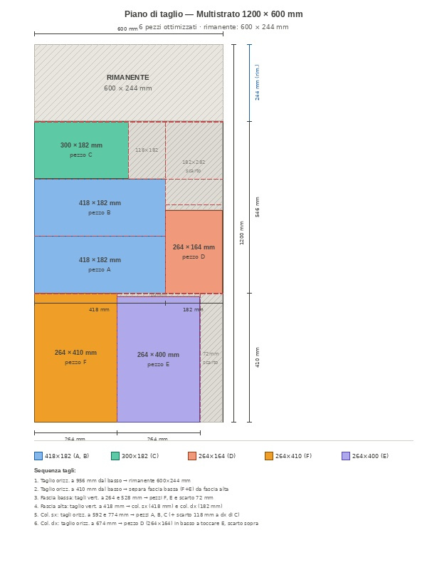
With the dimensions locked in from the 3D model, the next step was to work out the most efficient way to cut all the panels from the plywood sheet while keeping waste to a minimum. For this I used an AI program to work out the optimal arrangement of the pieces, resulting in the cut layout shown in the photo. From a single 47" x 24" (1200 x 600mm) sheet, 6 optimized panels were cut with minimal waste. The cut plan also includes the recommended cutting sequence — essential for making the cuts in the right order at the table saw.
Cutting the Panels: From a Single Sheet to Individual Pieces
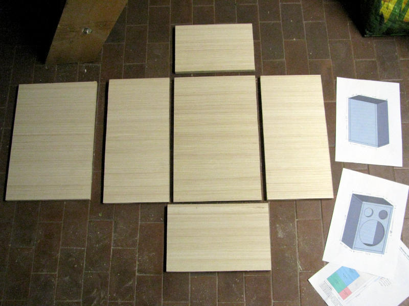
Following the optimized cut list, the plywood sheet was cut using my combination miter saw/table saw, yielding the six panels needed for the cabinet build. As you can see in the photo, the pieces have been laid out on the floor in their final relative positions — a quick visual check that makes it easy to verify dimensions and proportions before moving on to the next stages. Next to the panels you can see the printed 3D model and cut list, used as reference throughout the entire cutting and assembly process.
Biscuit Joinery: The Key to an Airtight Speaker Cabinet
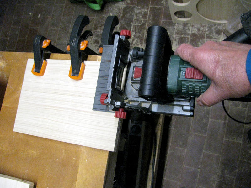
For joining the panels I went with biscuit joinery — a system that delivers solid, precise and perfectly aligned joints. The Parkside biscuit joiner shown in the photo is an inexpensive but highly effective tool for this kind of work: all the slots needed across every panel can be cut in just a few minutes. This joining technique, combined with generous amounts of wood glue during assembly, is essential for achieving a fully airtight cabinet — a non-negotiable requirement for an acoustic suspension woofer to perform correctly.
For those who don't have a biscuit joiner, the same result can be achieved using dowel joints. A step-by-step guide to this assembly method can be found in this article: Building Furniture Using Beech Dowels or Doweling
Gluing and Clamping: the Cabinet Takes Shape
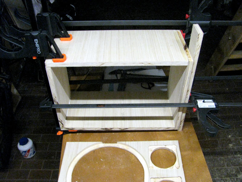
After a dry fit to confirm everything lined up correctly, it was time for the final glue-up. The biscuits were inserted into their slots with generous amounts of wood glue applied to all mating surfaces, then the panels were assembled and clamped up with woodworking clamps and left to cure overnight. In the photo you can clearly see the assembled cabinet structure with the clamps still in place. In the foreground you can also see the front panel, already machined with the speaker cutouts — the preparation steps for this will be covered in the next few sections.
Marking Out the Front Panel: Speaker Cutouts and Recesses
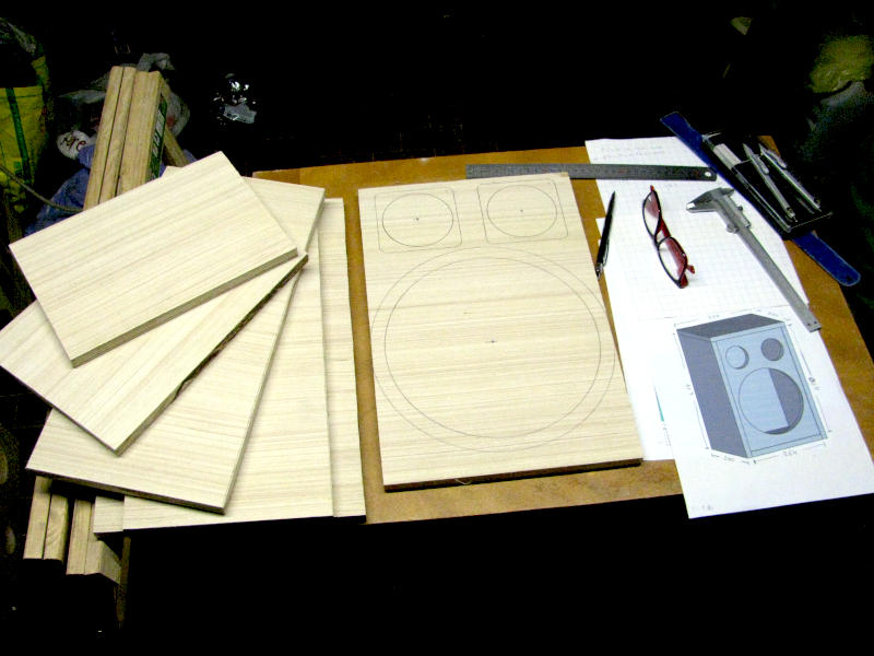
Before any machining could begin, all the cutouts and recesses needed to be carefully marked out on the front panel. As you can see in the photo, the circles for the speaker pass-through holes have been drawn onto the panel — the large circle for the 10" (25cm) woofer and the two smaller circles for the midrange and tweeter. Along with these, the outlines of the recesses have also been marked out: these will allow the speakers to sit flush with the front panel surface once installed. On the workbench you can see the tools used for marking out: a metal ruler, a caliper, a pencil, and the technical drawing exported from the FreeCAD model as a reference.
Routing the Woofer Recess: an Improvised Circle Jig That Actually Works
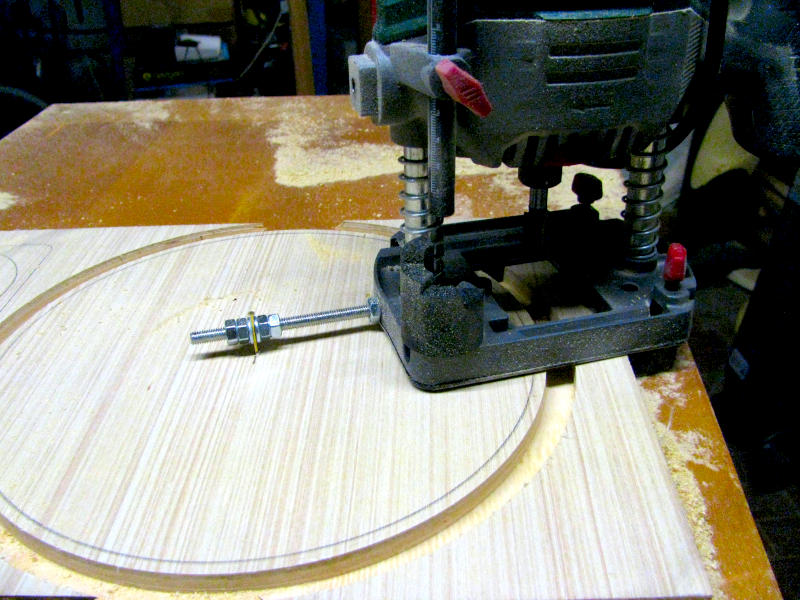
To rout the circular recess for the 10" (25cm) woofer, I used the router with a simple but surprisingly effective improvised circle jig: a threaded rod screwed into the threaded hole on the router base, secured to the center of the circle with a nut and a small picture-hanging nail. This setup, put together from spare parts, allowed the router to be guided precisely around the circular profile of the recess, delivering a clean and consistent result — all without the dedicated circle jig attachment, which couldn't be used for a circle of this diameter.
Cutting the Speaker Holes with the Jigsaw
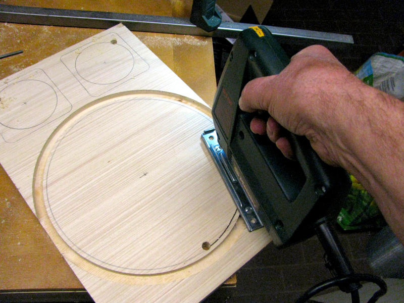
Once the woofer recess had been routed, the speaker pass-through holes were cut using a jigsaw with a narrow blade, allowing the tool to follow the circular profile of even the smaller speakers with precision. The sequence of operations was deliberately different for the woofer compared to the other two speakers: for the woofer, the recess had to be routed first and the pass-through hole cut second, since the improvised circle jig requires the center section of the panel to still be in place to anchor the centering nail. For the midrange and tweeter, on the other hand, it was more practical to work in reverse order — cut the pass-through hole with the jigsaw first, then rout the square recesses using the router with a straight edge guide.
The Completed Front Panel: Speaker Cutouts and Recesses All Done
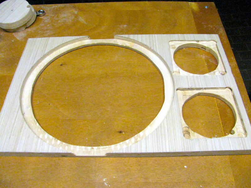
With all the routing and cutting complete, the front panel is now ready with all three speaker housings cleanly executed: the large circular recess for the 10" (25cm) woofer on the left, with its routed lip that will allow the speaker to sit perfectly flush with the panel surface, and the two square recesses for the midrange and tweeter on the right, each with their own routed lip. The precision of the recesses will ensure a clean speaker installation and a professional-looking finish once the metal grille is applied.
Painting: Primer and Matte Black Paint Applied with a Roller
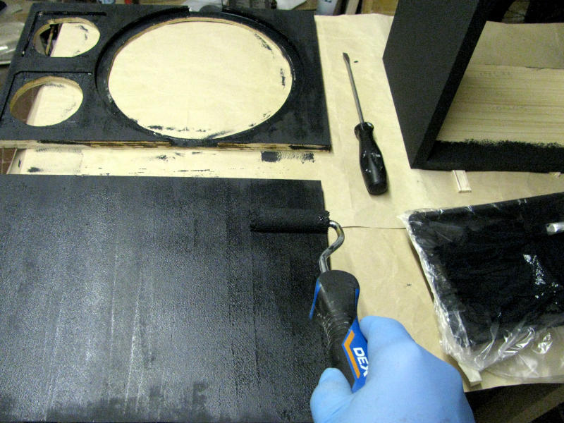
Before mounting the speakers, all the panels were painted separately — a practical choice that makes applying the paint considerably easier than painting the fully assembled cabinet.
The painting process involved the following steps: a first sanding of the wood surface with 220-grit sandpaper (roughly equivalent to European grit 600), followed by two coats of water-based wood primer to seal the plywood grain and prepare the surface for the topcoat, with a light sanding between each coat to improve adhesion. Once the primer had fully dried, two coats of water-based matte black paint were applied. A short-nap roller was used throughout, delivering a smooth and streak-free finish that works particularly well on the flat surfaces of plywood.
Mounting the Speakers: Bolts and Lock Nuts for Vibration-Proof Fastening
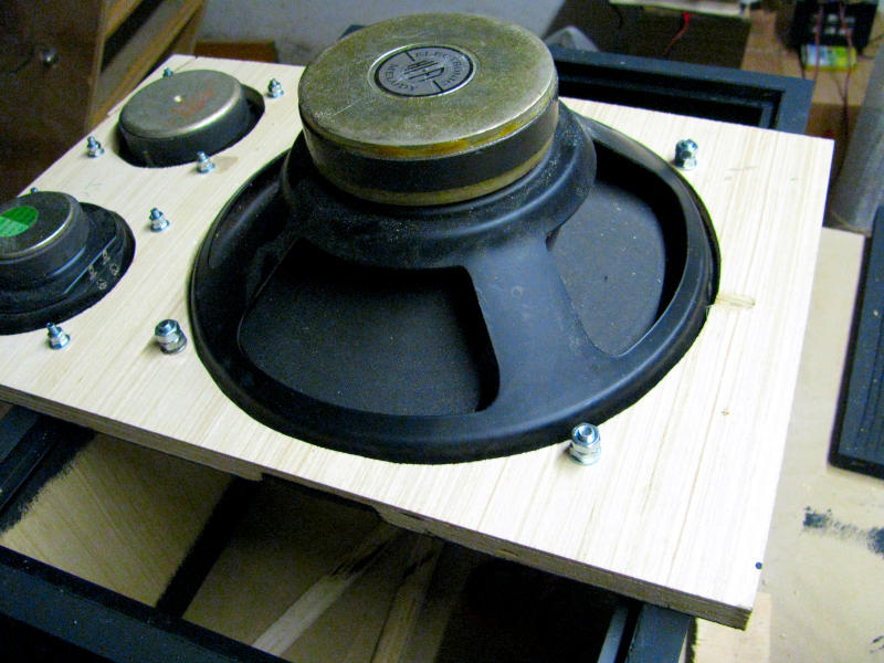
With the paint fully dried, it was time to mount the speakers onto the front panel. Rather than simple wood screws, I went with bolts and lock nuts — a more robust fastening solution that holds securely over time despite the vibrations generated during use. The lock nut, tightened down against the main nut, prevents the progressive loosening that vibrations would inevitably cause with a conventional fastening system.
Stapling the Metal Speaker Grille with a Pneumatic Staple Gun
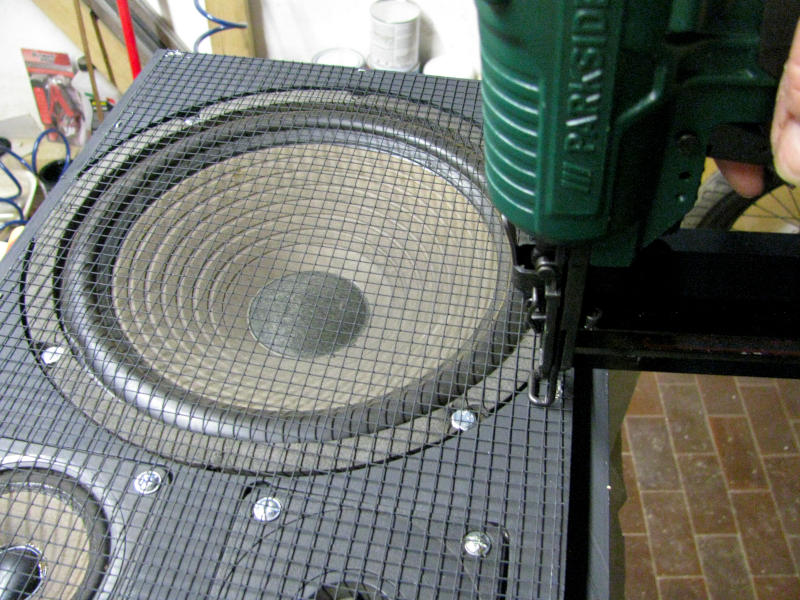
The metal speaker grille — previously painted black along with the other panels — was secured to the edge of the front panel using staples fired with a Parkside pneumatic staple gun. A pneumatic staple gun is the ideal tool for this job: it drives staples precisely and in rapid succession, ensuring a consistent hold all the way around the perimeter without any risk of distorting the grille mesh. Those without a pneumatic staple gun can get a similar result with a heavy-duty manual staple gun, or alternatively with U-shaped tacks hammered in with a lightweight hammer. As you can see in the photo, the grille was applied directly over the already-mounted speakers, covering the entire front panel surface evenly.
The L-Shaped Trim and Draft Seal Strip: the Front Panel Solution
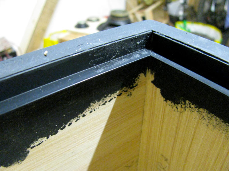
To recess the front panel inside the cabinet so that the grille edges would be completely hidden and flush with the sides, a 10x10mm black plastic L-shaped trim was glued around the entire inner perimeter of the cabinet. The front panel rests on the horizontal leg of the trim and is secured from the inside with screws, while the staples holding the grille remain completely out of sight. On the face of the trim where the front panel rests, a rubber draft seal strip — the same type used for weatherstripping windows — was also glued in place to ensure an airtight seal, a critical requirement for the acoustic suspension woofer to perform as intended.
The Amplifier Board Cutout: Routing the Top Panel
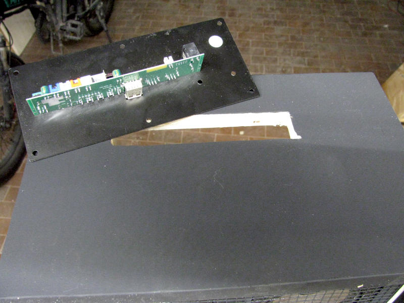
To house the amplifier board, a rectangular cutout was made in the top panel of the cabinet using a drill and jigsaw. The board is mounted on a black metal plate that acts both as a bezel and as a support bracket, secured to the top panel with screws.
The Internal Airtight Box Under the Amplifier Board: a Detail You Can't Overlook
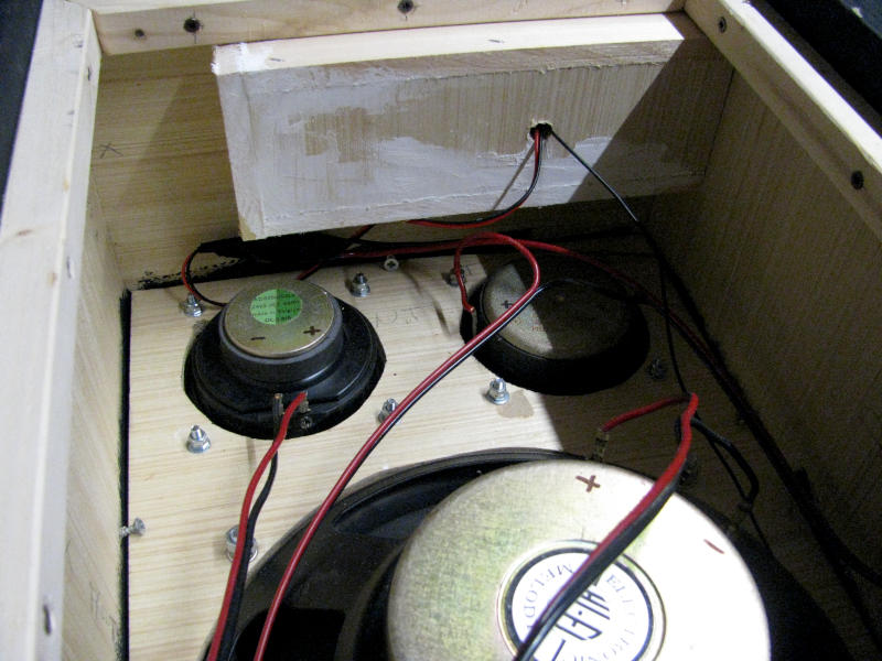
One important construction detail that's often overlooked in similar builds involves maintaining the airtight seal in the area around the amplifier board. The board has multiple holes and openings in it, and without adequate isolation it would compromise the cabinet's seal, making the acoustic suspension system ineffective. The solution was to build a small wooden box to sit inside the cabinet directly beneath the board, physically separating the amplifier compartment from the internal volume of the speaker cabinet. As you can see in the photo, the box is clearly visible at the top, glued and screwed to the top panel. The cable pass-through hole — where the red and black wiring connecting the board to the speakers runs through — was then carefully sealed with silicone to ensure a complete airtight seal.
Internal Wiring: 3-Way Crossover and Speaker Connections
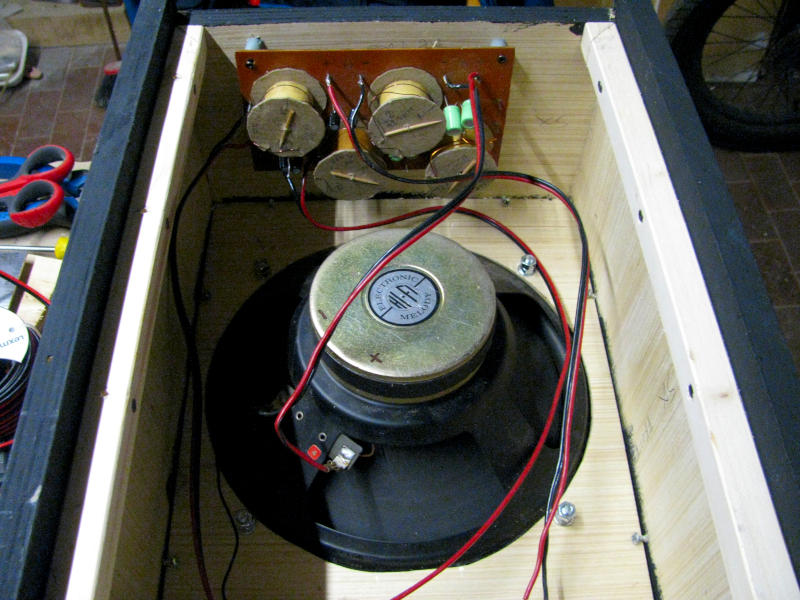
With the cabinet open at the back, you can clearly see the complete internal layout before final assembly. At the top, the hand-built passive 3-way crossover is clearly visible — salvaged from the same speaker cabinet as the drivers themselves, and given a new lease of life in this build.
One important detail about the amplifier board is worth highlighting: the board has two separate audio outputs. The first — used in this project to drive the 3-way crossover — carries the full frequency response of the amplifier. The second output is fitted with a high-pass filter and is specifically designed for connecting a tweeter, a necessary precaution since — unlike a woofer, which naturally rolls off high frequencies due to its mechanical characteristics — a tweeter fed the full frequency range would risk being permanently damaged. This means that anyone wanting to build a simpler version with a single full-range speaker won't need an external passive crossover at all, while those going with a two-speaker setup — a woofer and a tweeter — can take advantage of both outputs directly, again with no additional components required.
The rear panel was finally secured from the outside with screws onto the perimeter strip visible in the photo, also fitted with a rubber weatherstrip seal to ensure a fully airtight cabinet.
The Completed DIY Bluetooth Karaoke Speaker: the Finished Result
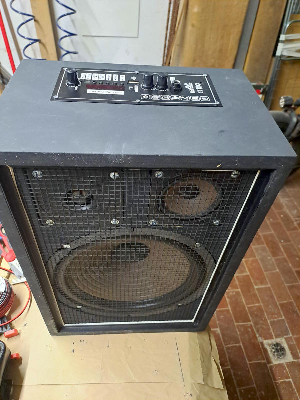
And here it is — fully assembled and ready to rock. The DIY Bluetooth karaoke speaker has a clean, professional look: a smooth and uniform matte black finish, a metal grille that lets the speakers show through, the black trim neatly framing the front panel, and the Bluetooth amplifier board with its controls cleanly integrated into the top panel. A result that holds its own against any commercial product in the same price range, built entirely from salvaged components, budget parts and a healthy dose of creativity — for a total cost well under the $200 price tag of the commercial unit that first inspired the project.
Conclusions and Acknowledgements
And there we have it — the DIY Bluetooth karaoke speaker is complete, up and running, and ready to liven up the next get-together with friends. As you've seen, this is a project that takes a bit of patience and a reasonable familiarity with basic woodworking and electronics, but one that more than pays off in the end — both in terms of personal satisfaction and the money saved compared to buying a commercial equivalent.
The real strength of this build is its flexibility: the speakers, the amplifier board and the cabinet dimensions can all be adapted to whatever components you have available and your own specific needs.
If you've found this guide useful and would like to explore more hobbyist electronics projects, feel free to browse the other content in the Electronics and Robotics section of the site, where you'll find plenty more practical guides and step-by-step tutorials.
I care a great deal about the quality and originality of everything I publish, so I'd rather my content wasn't copied or republished elsewhere. That said, if you think this guide could be useful to other people, I'd be really happy if you shared the link to this page — it's the best way to spread the word and support the work that goes into every article.
Happy Building, Everyone!
Luciano (Capitan Farloc)